Balloon Launch
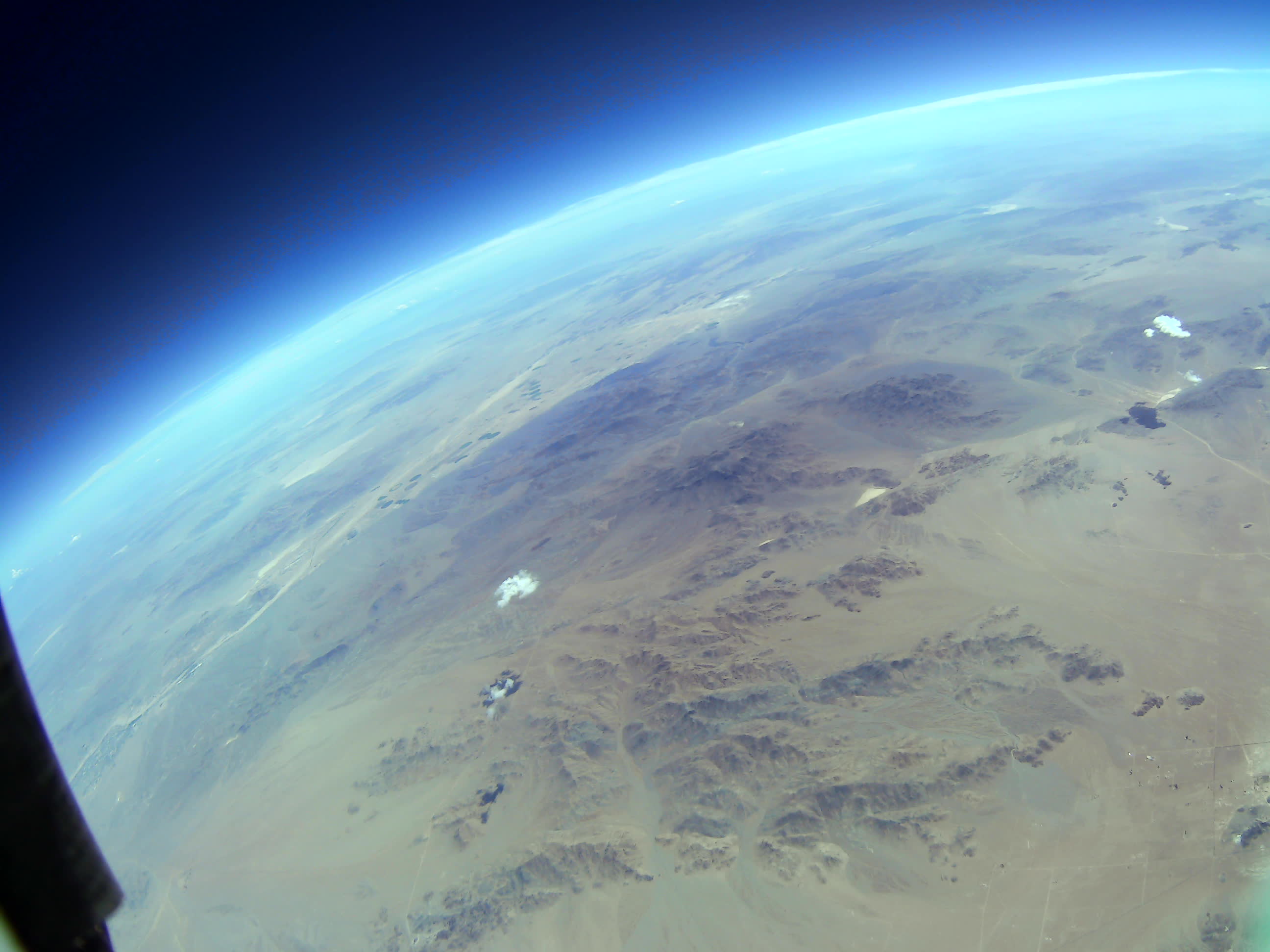
We’ve developed an experiment that flew on board of a balloon at an altitude of 90,000 ft (28 km). The goal of the experiment was to test the main subsystems of a future autonomous glider that could fly back to the launch site. The tested subsystems are:
All the plots shown in this document are in SI units with temperatures in Celsius, unless otherwise specified.
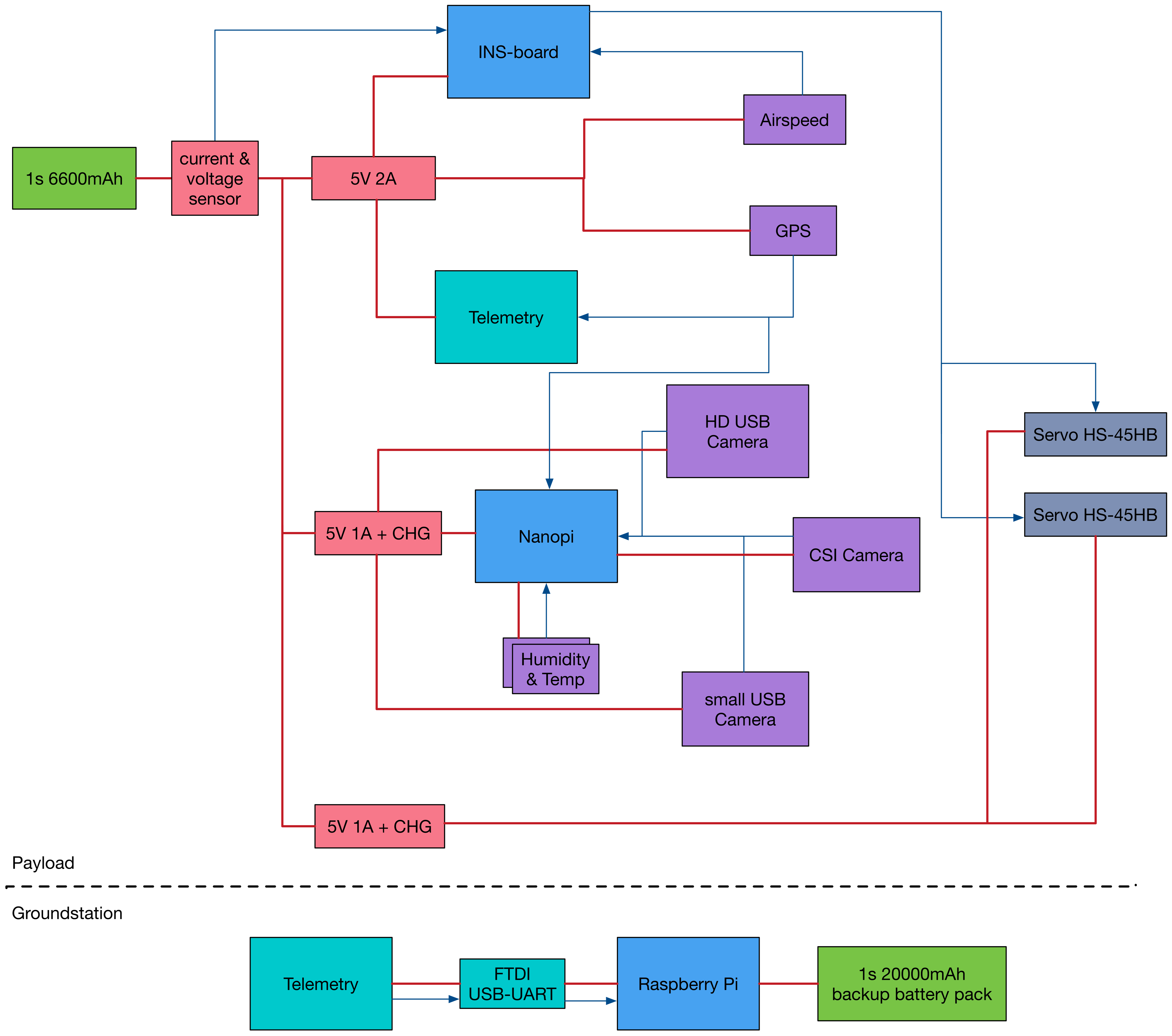
The diagram of our experiment can be seen in the next picture.
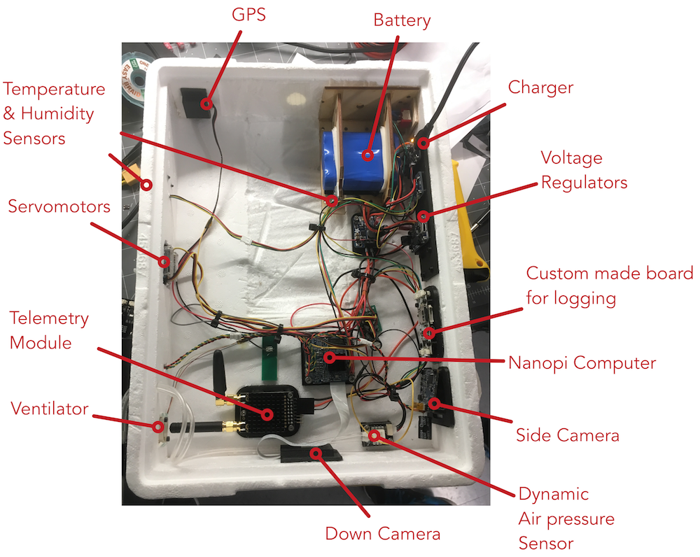
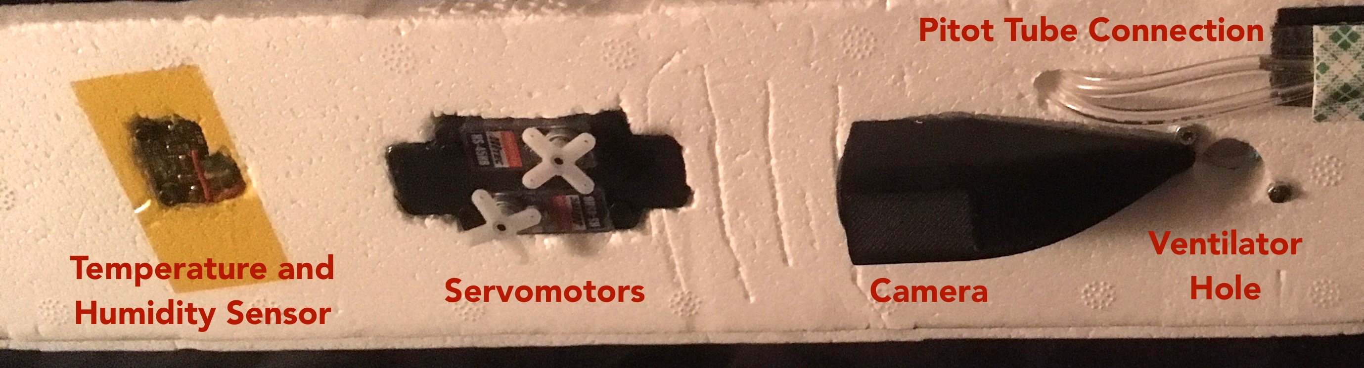
The implementation of our experiment can be seen below. We wanted to take a better picture but Patrick thought I will take one, and I thought Patrick will take a picture, so, as it usually happens in life when you don’t make someone responsible for a certain task, none of us took a better picture.
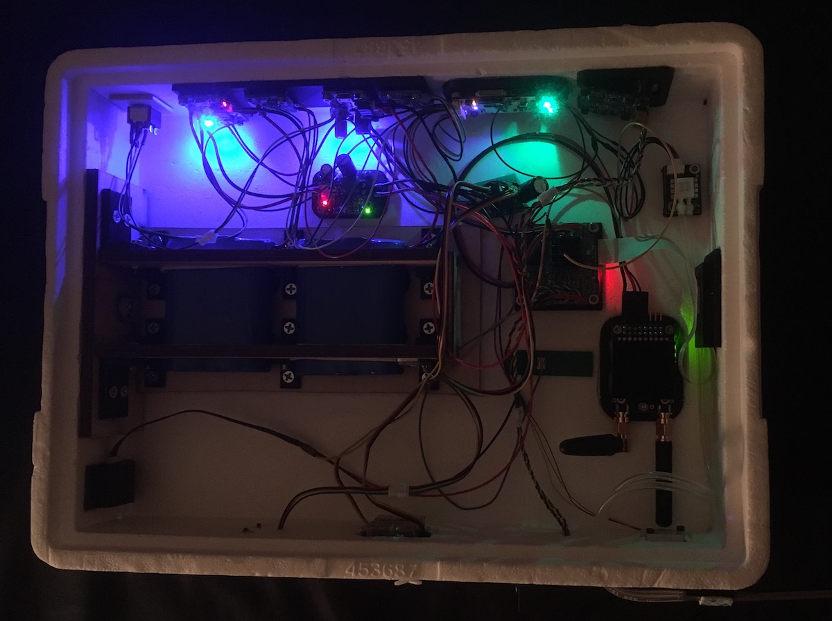
During one of the flight meetings, I found out that our experiment can weight at max 566 grams, and currently we had 850 grams. That was 2 days before the actual launch. So I took the experiment and went to the machine shop at Caltech trying to look for a solution. The battery pack together with its mounting was weighting about 400 grams, so I knew where I had to cut. The issue was that the battery pack was glued into the foam with epoxy, so it was kind of impossible to remove it. Bruce, our machine shop technician pointed out that there is a foam knife at Michaels. So I ran to pick it up. As luck would have it, it was the only one in stock.
That’s the reason why our experiment looks like this (huge hole in the center). It was quite disappointing to see the experiment with a hole in the center because we’ve spent huge amount of time trying to make it perfect.
We reduced the weight to 560 grams. Luckily, they also postponed the launch for Friday (instead of Thursday), so we had some time to sleep. We’ve built the experiment from 7pm until 12-1ish every day for a week, so we needed sleep a lot.
Power and power management system
For the power, we have used Lithium Ion batteries, 3.7v 6600mAh from Adafruit. They include a protection circuitry that keeps the battery voltage from going too high (over-charging) or too low (over-use) which means that the battery will cut-out when at 3.0V. It will also protect against output shorts. The battery was connected to two integrated boost converters also from Adafruit that were used to, on one hand charge the experiment and one the other hand to provide 5V to most of the electronics and servomotors.
What we have observed:
- the battery worked as expected. When the experiment landed, the battery had a voltage of 3.7V.
- the converters worked as expected
- overall the experiment consumed 1A in average, with peaks going up to 1.5A. The peaks were when cameras were recording, which was around every 3 minutes.
Below, we see the current and voltage plots of the battery during the entire flight, correlated with the temperature.
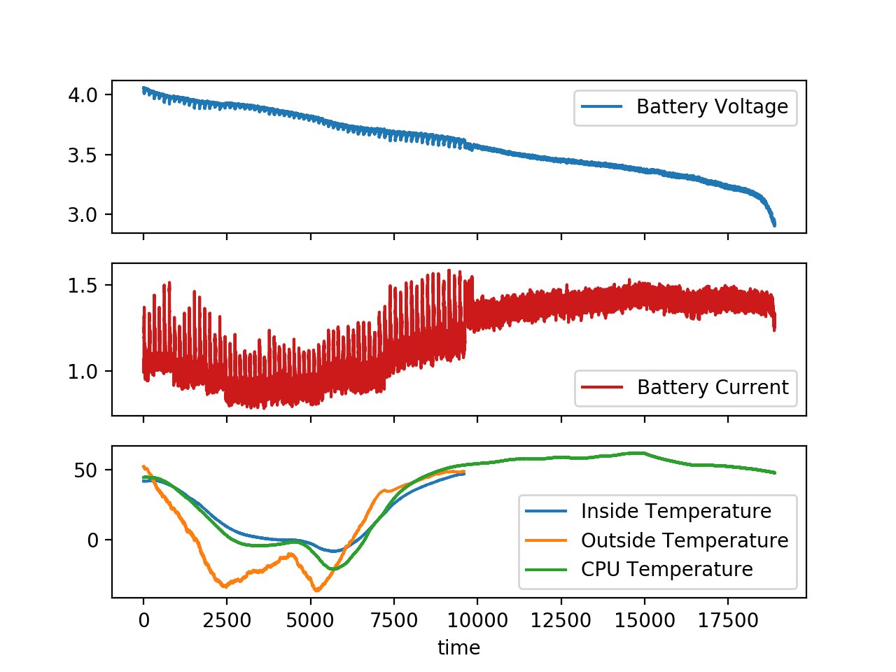
As seen in the top plot, the battery is approximately 4.1V when the experiment is turned on. The voltage drops that are seen in the plot are due to the video and pictures taken at a certain interval. When the experiment lands on the ground, the voltage is 3.7 V. With time, the voltage drops under 3.0 V and the battery shuts down, as expected.
In the middle plot, we can see the current plot. The same current spikes can be observed when cameras are taken video and pictures. We can observe a correlation in the current and temperature consumption.
In the bottom plot, we can see the temperatures as read by the temperature sensor placed inside the experiment box and outside the experiment box. The third temperature is the STM32 internal (CPU) temperature sensor.
Shortly before 10,000 seconds, the NanoPi stopped working for an unknown reason. Because of this, the cameras as well as the external temperatures sensors stopped recording. It is likely that the NanoPi stopped working because of overheating. Just before it stopped working, it consumed the recording current for a few minutes and then fell back to a slightly higher than idle current. After we retrieved the experiment several hours later, the NanoPi and cameras were still functional after we recharged the batteries.
Servomotors
One of the tests of this experiment was to see how servomotors (Hitec HS45) are behaving during a balloon launch. The servomotors will be further used to control the control surfaces of an airplane.
A camera was filming the servomotors 20 seconds every 2 minutes. The servomotor position was programmed to do a sine wave continuously. We have analyzed the images and we’ve seen no anomaly. The second servomotor was not connected anymore because of the change in power supply requirements (reducing the number of batteries from 2 to 1).
Check below a fast-forward movie of how it behaved.
From the movies, we can observe the following facts:
- in total, we had 63 movies, meaning that the camera recorded for 2.7 hours
- the camera recorded also after landing; however, it was not recording during recovery. The servomotors were still moving when the experiment was retrieved from the ground by the recovery team after 4 hours and 10 minutes.
- the parachute was oscillating a lot in the high altitude phase (from barometer data below, the airspeed was 35 m/s (126 km/h)).
Sensors
Barometer
The barometer used is MS5611-01. From the pressure, the altitude was computer using the NASA Paper Standard Atmosphere - Tables and Data for Altitudes to 65800 feet.
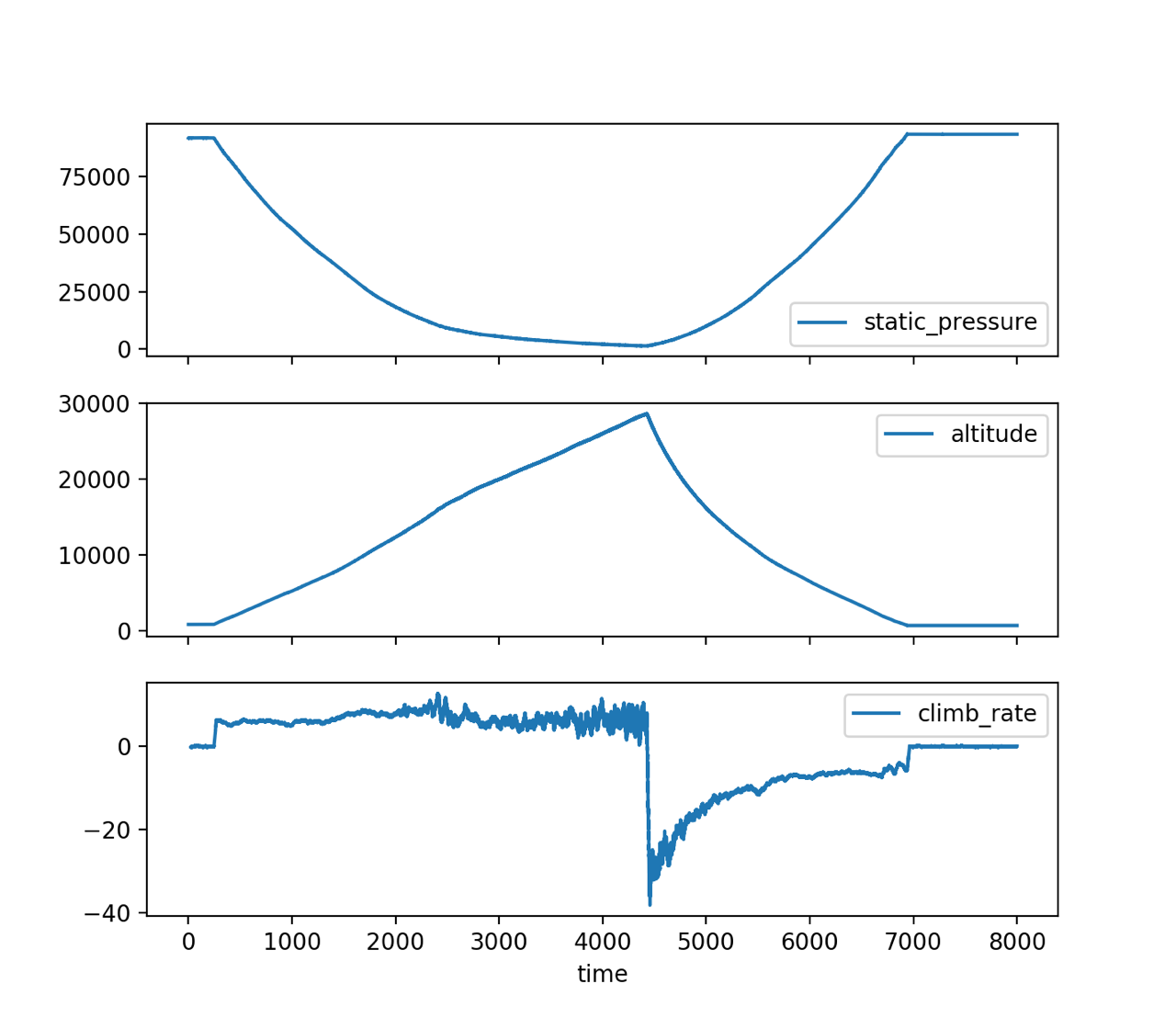
In the first plot, we can see the static pressure as a function of time. In the second plot, the altitude was computed. The apogee of the balloon was 28,600 meters (93,832 feet). From the altitude, the climb rate was computed. Afterwards, a filter was applied. The balloon climbs up with a constant rate of about 7 m/s. Initially, after the burst, the experiments fall with a velocity of about 35 m/s (126 km/h). The experiments touch down with a velocity of 6 m/s.
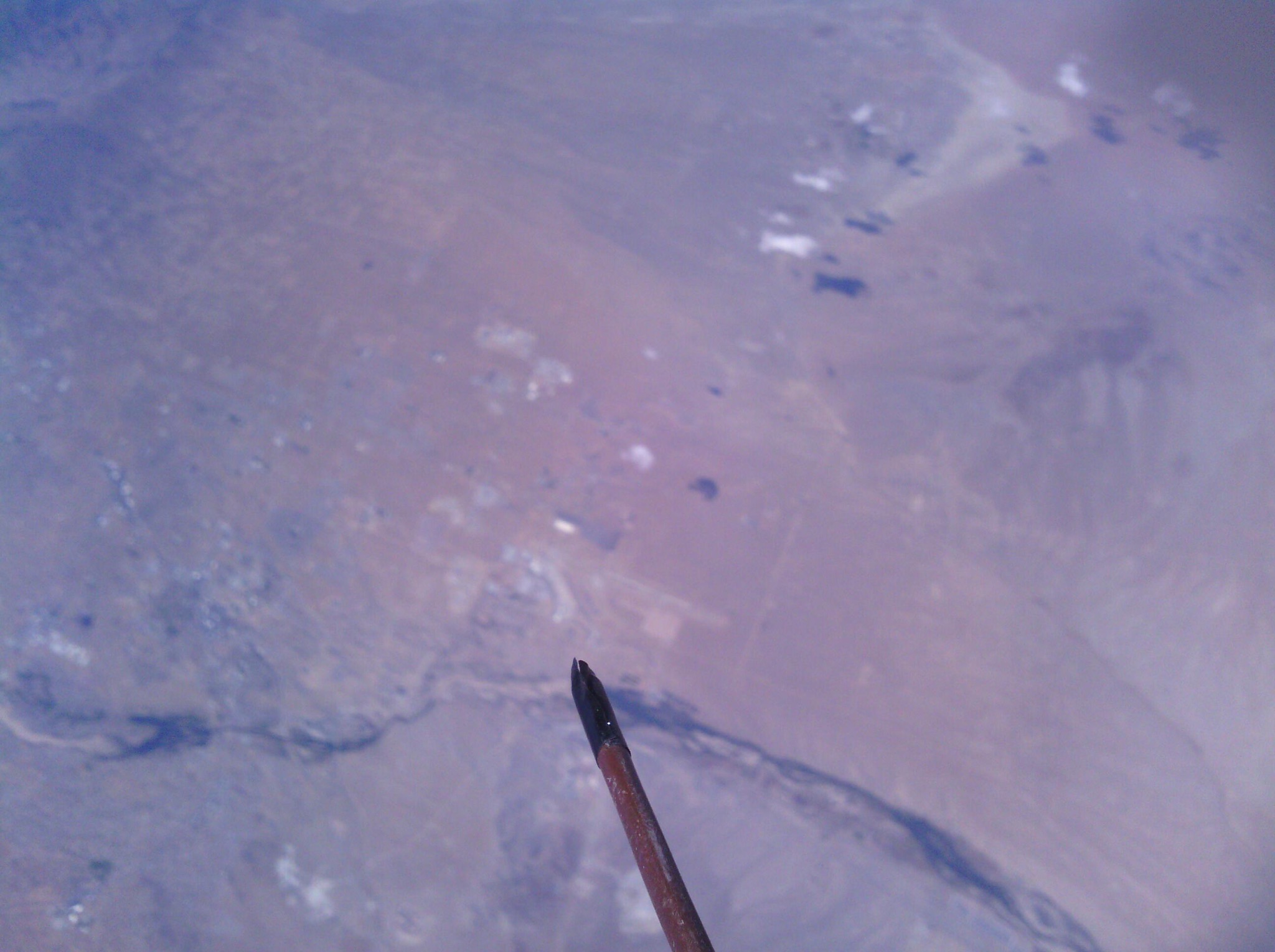
Dynamic Pressure Sensor
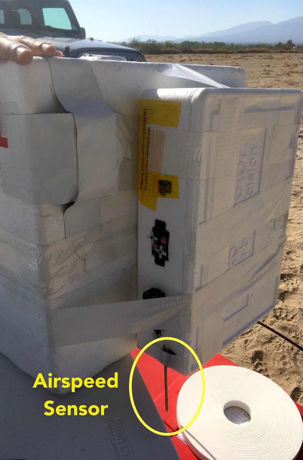
The dynamics pressure sensor will be used to measure the airspeed of the glider. For this experiment we mounted it facing down to measure the sink rate during descent. The Pitot tube that goes to the differential pressure sensor was mounted as in the picture below. The dynamic pressure sensor used was MS4525DO.
Below, we can see the plot of the altitude profile and climb rate. From the climb rate, the expected dynamic pressure is computed, by using the density from the same atmospheric model as in Barometer sensor. We can observe that the parachute drops with constant dynamic pressure, as expected. The dynamic pressure as measured from the pitot is seen in the bottom plot. The noise is too high to read any significant data from the dynamic pressure sensor.
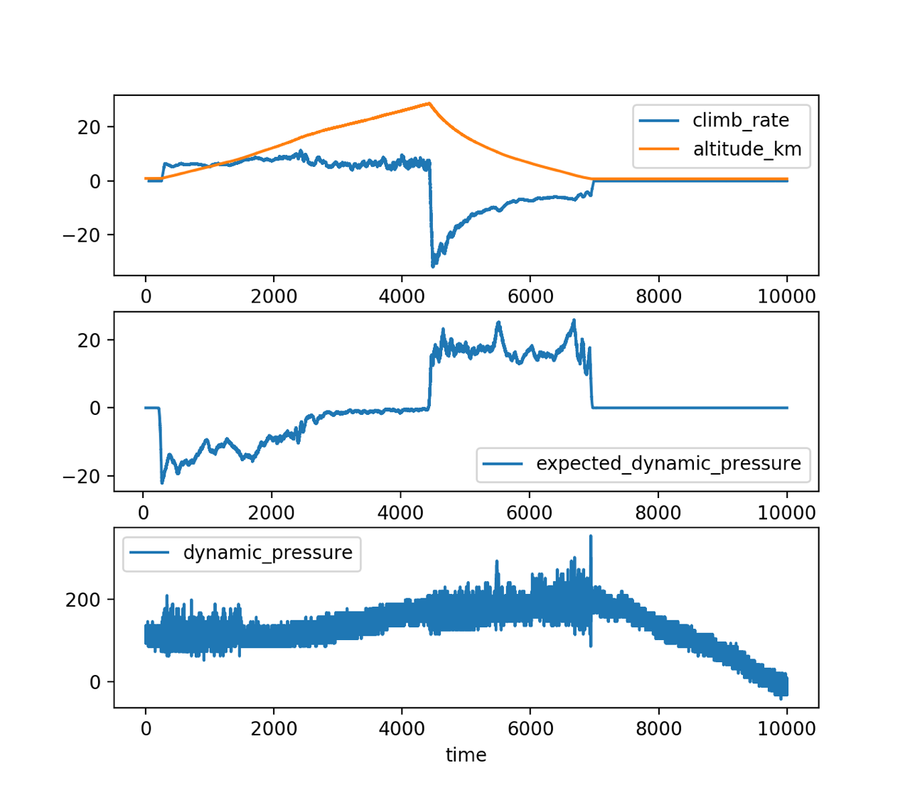
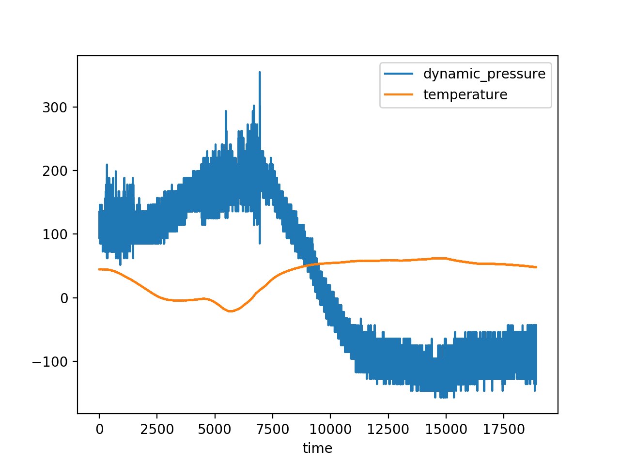
From this second plot, we can observe that the bias of the pressure sensor changes with temperature.
IMU
The IMU used was MPU 6000. The IMU was logged on the SDCard using the INS (Inertial Navigation System) board, a custom-made board developed by Patrick some time ago. Below, there is an example of data at the apogee of the balloon.
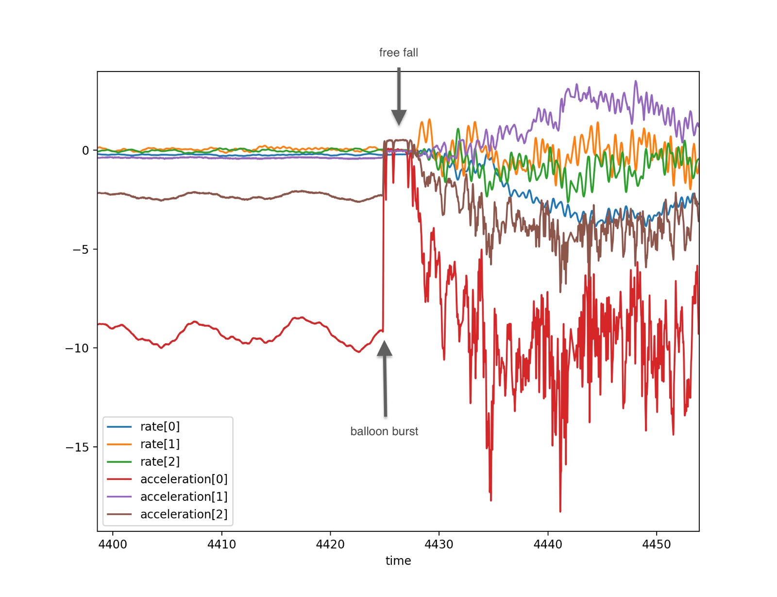
What did we observe:
- when the balloon bursts there are 3 seconds of low gravity (falling) before the experiments start decelerating on the parachute
- the IMU logged during recovery (there is a peak in acceleration when the experiment was picked up from the ground)
- the last phase before the balloon burst was pretty smooth, however, we can observe some vertical oscillations from the fact that the balloon and cord are elastic.
GPS
The GPS data got recorded on an SD card as well as transmitted to the ground station using the RFD900 telemetry module. The GPS used was Ublox SAM-M8Q.
In the image below, the coordinates were plotted in 3D.
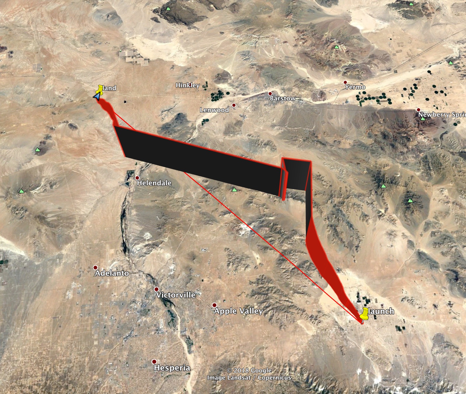
What did we observe:
- The balloon traveled 69.6 km on horizontal
- In the previous plot, there is a gap in GPS data. The GPS was on default configuration because the version we had did not have external memory to store new parameters. The default configuration was Portable mode. However, this mode has an altitude limit of 12000 meters. The correct configuration should have been Airborne which is the suitable configuration with higher range and vertical acceleration. The maximum altitude is 50000 meters, which would have been higher than the balloon’s altitude.
Computer running Linux
The computer we chose was the NanoPi Air because it is compact and has a camera interface.
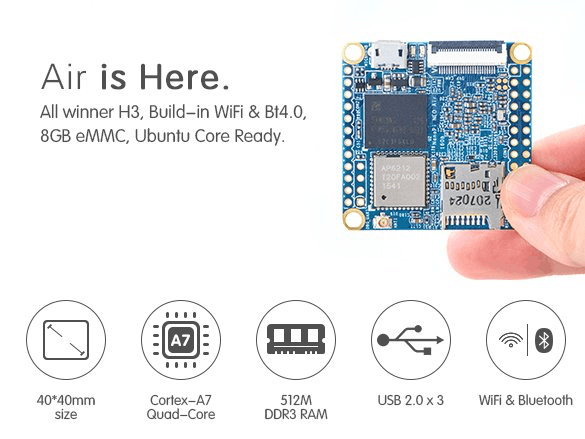
The computer was running a script to record the images, the videos, the GPS and temperature and humidity sensors. The script can be seen here.
The NanoPi Air stopped working after 2.7 hours while laying in the sun after the flight (most probably due to overheating).
We mounted a small fan to circulate the air inside the box but it was probably not enough. The fan was ON whenever the temperature was more than 30 degrees C.
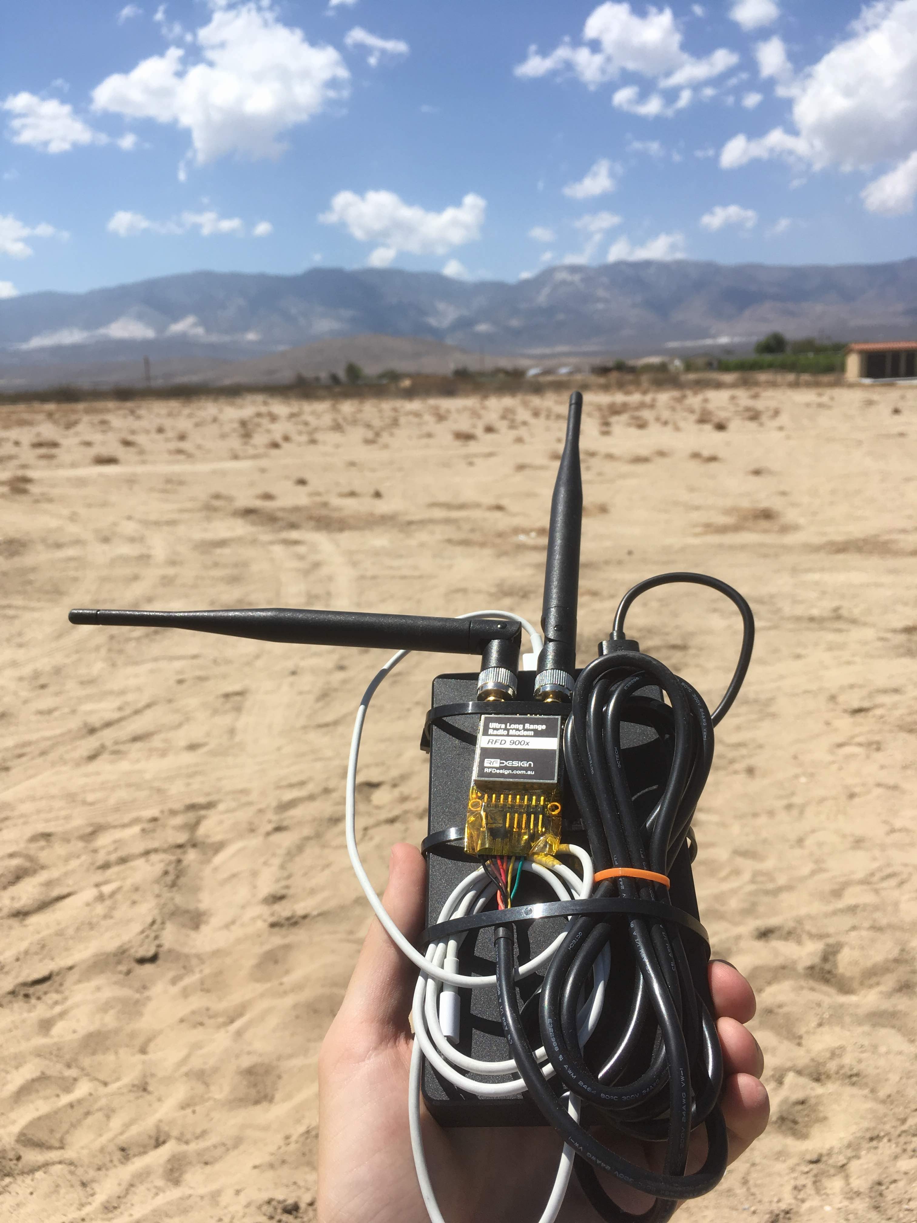
Telemetry
For telemetry, we used the RFD900+ Radio Modem.
The settings we used were:
- airdata rate = 64 kb/s
- ECC ON (checksum)
- maximum power = 30 dBm
The continuous telemetry was lost at a bit over 20 km, but we still got sparse packets, the last one at 58 km horizontal distance. The other payloads were not transmitting at the same frequency but we were not checking the signal quality after integration.
For the ground station, we implemented a web-server running on the Raspberry Pi. It displayed raw NMEA message and also created a weblink that could be opened in Google Maps Offline mode on the mobile phone. We attached a backup 20Ah battery to the Raspberry Pi. We did not want to use laptops because we are in the desert.
Cameras
| Model of camera | Description |
|---|---|
| CAM500B - 5MP 1080p Camera Module with OV5640 Chip | The camera was interfaced with the NanoPi and was pointing down |
| HD 720P Mini Micro USB 2.0 Endoscope Inspection Camera | The camera was used to film the servomotor test |
| ELP-USB800W02G-L170 | The camera was pointing on the side |
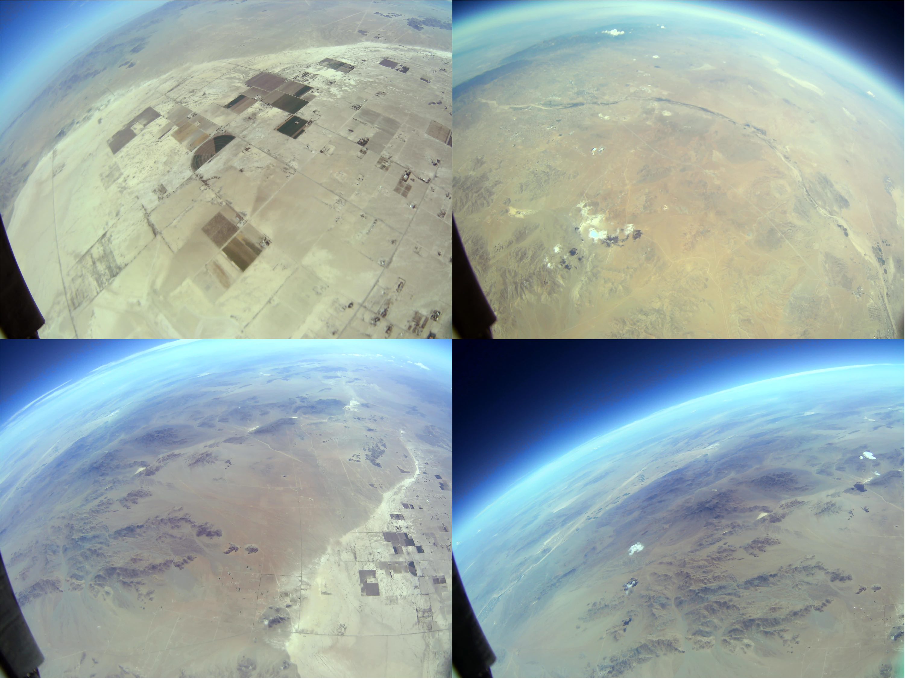
Below, there is a picture of the CAM500B camera. This camera had autofocus. When we mounted our box to the main box, we haven’t noticed that the antenna of the other experiment was in the field of view of the CAM500B. As the camera was on autofocus, it focused on their antenna during the entire flight :(.
The next collage is from the ELP-USB800W02G-L170 camera. The power supply was very noisy because of the telemetry module and the servos on the same battery, and the camera is very sensible to stable power supply. We added a capacitor to improve that however, from the entire flight we had only 10 images.
Conclusions:
We are happy with the results, considering that we put the experiment together in very short time. It was good that we could fly together with another payload, so we didn’t have to worry about the organizational parts. We were also relaying on their telemetry and recovery.
The lessons learned:
- For telemetry, we should get a higher gain antenna and reduce the data rate to achieve reliable telemetry during the entire flight
- The GPS should be configured correctly
- Better thermal management (in our case bigger fans and heat sinks)
- Design better power supply to handle high current peaks of the telemetry module (from measuring on an oscilloscope, we got around 1.5 A)
- For the pitot tube sensor, we need to calibrate it with temperature or find a different one
- The servos were working correctly, but were a bit shacky when the power supply was low or unstable. We want to take digital ones that should be more stable.
- Disable autofocus, maybe also auto white balance and auto exposure